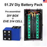
How To Assemblewistek 300ah Battery Pack
Step 1. Wheels Mounting
1Attach the Wheels: Use 16 M6 x 14 hexagon Phillips screws to mount the wheels, as illustrated in "Figure 1". Set the torque of the electric screwdriver to 8 Nm ,with a standard torque of 10 Nm, and tighten the screws until the electric screwdriver clicks.
2Apply Epoxy Insulation Boards: Remove the protective film from epoxy insulation boards A, B, and C, and adhere them to the inner sides of the box. Ensure they are positioned correctly, as shown in "Figure 2".
Materials:
1 pcs battery box and 4pcs wheel,
2 pcs Epoxy board A,
2 pcs Epoxy board B,
2 pcs Epoxy board C,
16 pcs M6 * 14 hexagon Phillip screws.
Tool:
Electric screwdriver
10mm sleeve and PH3 cross screwdriver
Step 2. Cell Placing
1. As shown in "Figure 1", Paste EVA foam on the surface of the cell to separate cells.
2. As shown in "Figure 2", Put the cells into the case. Paste epoxy board B to separate cell from cell, and cells from front plate paste epoxy board C.
3. Fix the front plate with six M8 *20 hexagon Philips screws as shown in "Figure 4" Set the torque index of the electric screwdriver to 12nm. (Standard torque: 25nm) until the electric batch clicks.
Material:
16pcs cells, 18pcs cell foams,
2 pcs Epoxy board A,
1 pcs Epoxy board B,
2 pcs Epoxy board C,
6pcs M8* 20 hexagon Philips screws.
Tool:
Electric screwdriver,
13mm sleeve and PH4 cross screwdriver
Note:
Due to different manufacturers of the cell tolerance, according to the instructions after the foam is still loose, increase the foam filling.
Step 3. Top Bracket Installation
1. As shown in "Figure 1", Paste EVA foam on the bracket and align the hole position.
2. As shown in "Figure 2", Fix the top bracket with eight M5 * 8 hexagon Philips screws. Set the torque index of the electric screwdriver to “6”.(Standard torque:6nm) until the electric batch clicks.
3. Install the aluminum row, as shown in "Figure 3" to install the serial aluminum row on the pole.
4. Place gaskets, such as "Figure 4" the gaskets are placed on the aluminum bar; B+, B- poles do not put gaskets.
Material:
2 pcs top bracket EVA foams,
2 pcs top brackets,
8 pcs M5* 8 hexagon Phillips screws,
30 pcs gaskets,
14 pcs EV-1 aluminum bar,
1 pcs SF-L1 aluminum bar
Tool:
10mm sleeve,
Electric screwdriver,
PH3 Phillips screwdriver,
Torque wrench
Step 4. Install PCB A/B board
1. Fix PCB A/B board with twelve M4 * 8 hexagon Phillips screws as shown in "Figure 1". Set the torque index of the electric screwdriver to “4”(Standard torque:3nm) until the electric batch clicks.
2. Connect the lug connectors with battery terminals at the corresponding position as shown in "Figure 1". Fix the aluminum bar with thirty M6 flange nuts. Set the torque index of the electric screwdriver to “10”(Standard torque:10nm).
Material:
2 pcs PCB board,
12 pcs M4 * 8 hexagon Philips screws,
30 pcs M6 flange nuts
Tool:
Electric screwdriver,
10mm sleeve,
PH3 philips screwdriver,
Torque wrench
Step 5. BMS Installation
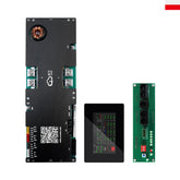
1. Install BMS: See figure to distinguish the support direction, install the BMS on the sheet metal support, use six M3*8 Phillips round head screws to lock, and electric torque set to"1"(Standard torque:1.2nm), until the electric batch clicks.
2. Installing a copper bar: As shown in the "Figure", the corresponding positions of the copper bar YS-0, YS-1, YS-3, and YS-5 are installed, and the torque of copper bar screws is adjusted to "6", (Standard torque:8nm), until the electric batch clicks.
3. The sampling cable, display screen, and adapter cable are wrapped with electrical tape and then inserted in the corresponding position as shown in the Figure.
Material:
BMS*1 PCS,
BMS bracket*1 PCS,
Copper bar: YS-0*1 PCS, YS-1*1 PCS, YS-3*1 PCS, YS-5*1PCS,
BMS wire 13P-135 black*1 PCS and BMS wire 13P-135 white*1 PCS,
Display cable*1 PCS,
M3 * 8 Philips round head screw sets(with washer and spring)* 6 PCS
Tool:
Electric screwdriver,
PH3 cross screwdriver,
PH2 cross screwdriver,
PH4 cross screwdriver,
Torque wrench
Step 6. Top Plate Installation
1. Top plate installation: As "Figure" installation connector socket *2; use eight M4*10 Hex socket flat head screws to lock, and adjust the torque of the electric batch to “5”(Standard torque:3Nm) until the electric batch clicks.
2. Install the adapter plate: Use three M3*8 Phillips round head screw to










Leave a comment
All blog comments are checked prior to publishing